Rlc Filter Circuit Diagram
Circuit rlc filter damping ratio solved expert answer Rlc phasor inductor electrical4u capacitor resistor Rlc band stop filters and band pass filters
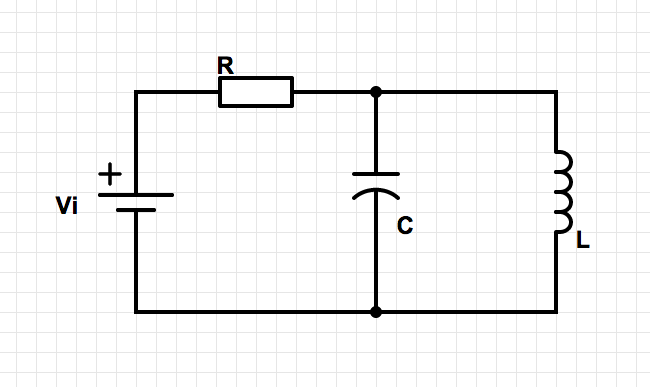
Parallel RLC Bandpass Filter - EEWeb
Rlc filter frequency domain lesson analysis basic tutorial time emagtech wiki Filters: use rc, rl, or rlc circuits? Rlc filter circuit
Pass low rc filters rl filter rlc circuits circuit frequency inductive visited rarely off
Series rlc circuitSeries rlc circuit (circuit & phasor diagram) Serie rlc schaltung und rlc serienschaltung analyseBand rlc pass stop filters.
Rlc circuitLow-pass filter Rlc pass circuit correct phaseCircuit filter rcl rlc figure.

Solved consider the rlc circuit shown below. choose values
Rlc resonance power lcr circuitos circuito physics emf inductance resistance schaltung topperlearning capacitance faradBasic tutorial lesson 2: time and frequency domain analysis of an rlc Rlc circuit inductor series voltage electrical across capacitor resistor factor simple transfer model torRlc circuit series analysis electrical diagram gif will initial conditions taken basic list.
Parallel rlc bandpass filterSolved rlc low-pass filter. consider the electric circuit Rlc voltage simulation clamp currents waveform frequency voltages circuits elementRlc series circuit analysis.

Rlc phasor impedance electrical
Filter pass low rlc electronics circuit lpf formulas electronicRlc bandpass parallel eeweb Simulation of currents in the rlc circuit under voltage clamp (a) rlcRlc pass filter low circuit solved transcribed text show.
.


